As a symbol of economic strength development, aerospace technology has been greatly supported by the state in recent years. A key indicator of aviation technology research and development is the design of the engine. In the past, China’s aero-engines relied on foreign imports, and the self-produced engines were difficult to spread throughout the field due to their defects. Careful research can be found that the manufacturing precision of key components of domestic engines is difficult to meet the design requirements, which has brought great obstacles to the development of aviation technology in China.
Since the advent of the finite element method, the accuracy and low cost of the calculation results have expanded its application in many fields. The integral impeller is one of the core components of the aero engine. Its structure is complex, the blade is thin and the distortion is large, and the blade spacing Small, often working under high temperature, high pressure and high speed conditions. Due to the particularity of the environment in which the application is used, the engine has certain requirements for the overall impeller machining.
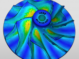
The finite element software of Ansys et al. focuses on the analysis of the impeller and the modal analysis. The self-vibration frequency and vibration mode of the impeller are obtained. Simright Simulator considers simplifying the impeller model to a static problem, imposes constraints on the center of the impeller, and applies surface loads to the impeller. The calculated results provide a basis for subsequent dynamic analysis. The impeller model is shown in the following figure. The curved surface is a non-expandable ruled surface. It can be modeled by three-dimensional software such as UG. The machining method is side-milling of five-axis CNC machine tools.

After introducing the model into the Simulator, the titanium alloy material is imparted. The titanium alloy has high strength, good corrosion resistance and heat resistance, and developed into a material for aero-engine parts as early as the 1960s. In addition, the surface load is applied to the model to simulate the impeller’s force rotation, and the center of the hole is used to constrain the fixed impeller. After the mesh is divided, the solution is submitted.


As shown in the figure above, the displacement cloud and stress cloud diagrams, the maximum displacement occurs at the top of the blade, and the maximum stress occurs at the root of the hole. It is known that the blade is most prone to deformation during the working process, which should be especially concerned during the field inspection.
As an online simulation software, Simright Simulator has laid its unique industry value. The pursuit of the simplification of the calculation process is the original meaning of its design.
Click to view item