There are many methods in mechanical transmission, which can be divided into two categories: one is to transmit power by friction, other is to realize the There are many ways of mechanical transmission, which can be divided into two categories: one is to transmit power by friction; the other is to realize the engagement between the active part and the driven part, such as gear transmission, which is widely used in machinery and ships. And the field of aerospace. Compared with other transmissions, the gear transmission has high precision and good efficiency, but the vibration damping and impact resistance are not as good as other transmissions. Therefore, failure modes such as gear breakage and tooth surface wear should be considered in the gear design. Gear breaks are usually broken due to repeated repeated bending stresses and stress concentrations; the other is overload breakage due to sudden severe overload or shock loading. In particular, gears made of brittle materials (cast iron, hardened steel, etc.) are more susceptible to gear breakage. Both fractures start on the side of the tooth that is subjected to tensile stress. Stress and strain analysis of the gear transmission process using finite element theory can help designers to improve the design plan in time to ensure the smooth progress of the project.
In the gear transmission process, the stress values of two aspects are mainly considered. One is the tooth surface contact stress and the other is the tooth root bending stress. These two stress values are important forms for judging the gear failure. Since the gear meshing transmission is a contact problem, the general finite element software simulation process is to first establish a model, create contact pairs, then mesh, apply constraints and loads, and finally solve. Simright is similar, but the operation is more concise. First, the external model can be directly imported, a fixed constraint is applied at the center of the hole, and a unit torque is applied to the gear mesh to simulate the transmission torque, as shown in the following figure.

After assigning the material properties and meshing them, you can submit the solution. After the completion, jump directly to the post-processing interface, as shown in the following figure.
According to the displacement cloud map and the stress cloud map, the displacement and stress changes under the current load can be seen, and then the gears are used to determine whether they meet the design requirements.


Click to view item
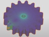
In addition, you can also view the meshing in the post-processing by right-clicking on the gear and selecting “Display Grid”. As shown in the following figure, it can be seen that the grid divided by the system’s own meshing technology is more regular.