Feeding equipment is more common in the fields of agricultural machinery and chemical machinery. Its main function is to transport the processed or processed materials to other stations through the feeding equipment, which is also the necessary equipment for the automation of the flow operation. Depending on the application, the feeder is also structurally different, common with vibrating feeder.
The working principle of the vibrating feeder is to generate centrifugal force by rotating the eccentric block in the vibrator, so that the movable part of the tank, the vibrator and the like can be forced to have a continuous circular or approximately circular motion. The material is slowly moved down along the inclined box surface, and the material is continuously and evenly sent to the receiving port to complete the feeding operation. During the working process, the vibrating feeder box is subject to fatigue damage due to the alternating load under the natural frequency. Therefore, attention should be paid to avoid stress concentration in the initial structural design, and the work efficiency can be improved while ensuring the reliability of the feeder. .
In the traditional method, Ansys can be used to perform modal analysis on the bin, calculate the natural frequency of the specified order, and perform dynamic analysis. The theory involved in modal analysis is more complicated and generally difficult for beginners to master. When using the Simright Simulator to design the material box, only the deformation of the material box under the material pressure can be considered, as shown in the figure below.

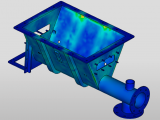
After the model is introduced into the Simulator, pressure is applied to the inner surface of the tank and the pipe, and the surface load is applied to the discharge port; the three degrees of freedom are fixed at the top of the bin, and the material is selected and the mesh is submitted for solution. The displacement cloud and stress cloud are shown below.


It can be seen from the displacement cloud diagram that the maximum displacement occurs on the connecting column on the side of the tank. From the stress cloud diagram, it can be seen that the stress distribution is concentrated on the bottom of the tank and the inclined surface. Therefore, it is considered to design a small pass at the slope or bottom of the tank during design. The holes avoid stress concentration and, in addition, avoid the risk of bending fractures on the side of the tank.