Mobile lifting platforms are widely used in many fields due to their convenience and practicality. Its mode of action includes cargo transportation, load bearing, take-off and landing, and is common in industrial installations, equipment maintenance and other operating environments. The scissor lifts are available in a variety of configurations, from low to high, and the number of scissor arms is also increased, so the installation is flexible. The lifting platform is mainly composed of a moving chassis, a scissor mechanism and a working plane, and is structurally symmetrical.
The scissor mechanism is one of the indispensable components of the mobile lifting platform. The compressive strength and geometrical design of the material must be reasonable to ensure the stability and reliability of the lifting platform. The design of the scissor mechanism is determined by the working environment and application. According to the allowable stress of the working plane, the appropriate material is selected as the support of the scissor mechanism. The finite element software is used to simulate the field condition analysis, and the calculation result can be used as the design material. Reference data at the time.
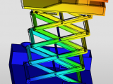
Traditional finite element software generally splits the large-scale components into small parts and analyzes them independently. The results obtained are also more precise, which is beneficial to the optimization of the organization, but it is time-consuming and labor-intensive. As a cloud finite element analysis software, Simright simulator has been dedicated to simplifying simulation, and the analysis process can be completed in a few simple steps. The results obtained also have certain engineering application value. Move the lifting platform as shown in the figure below. When analyzing, consider applying pressure on the working plane and applying a fixed displacement constraint on the moving chassis, thus simplifying the whole model into a common static problem.

After the material properties are assigned and meshed, the solution can be submitted. After completion, the post-processing interface is automatically entered. The displacement cloud map and the stress cloud map are shown in the following figure.

From the displacement cloud diagram and its undeformed profile, the downward movement distance of the working plane and the scissor mechanism can be seen. From the stress cloud diagram, it can be seen that the stress is at the root of the scissor mechanism. Therefore, the maximum root of the mechanism should be considered when designing the rod. Stress value.

The Simright simulator also provides animated display of displacement and stress variation results. To view it, just click on “Animation” under the function tree on the left.
Click to view item